I. Introduction
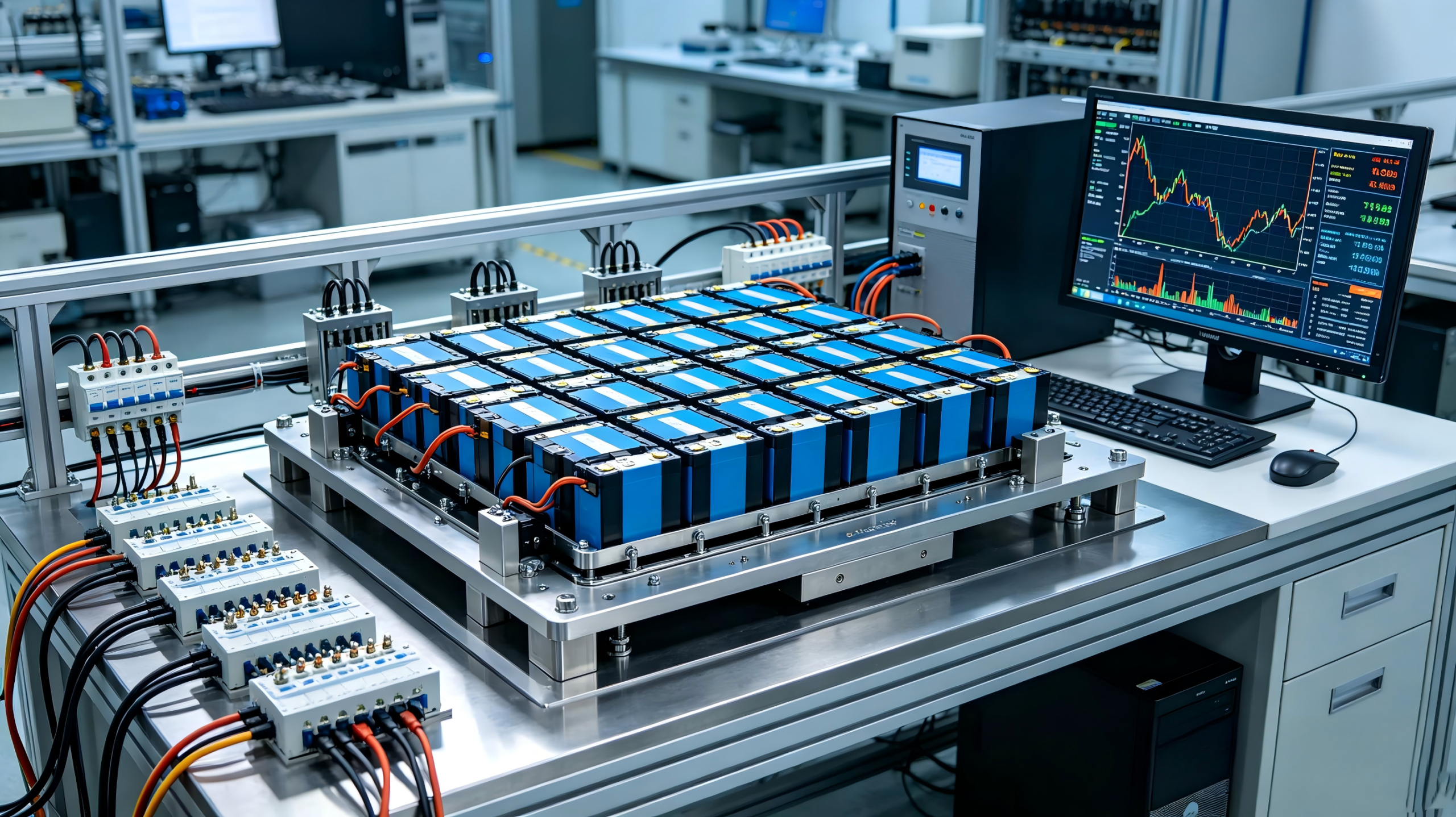
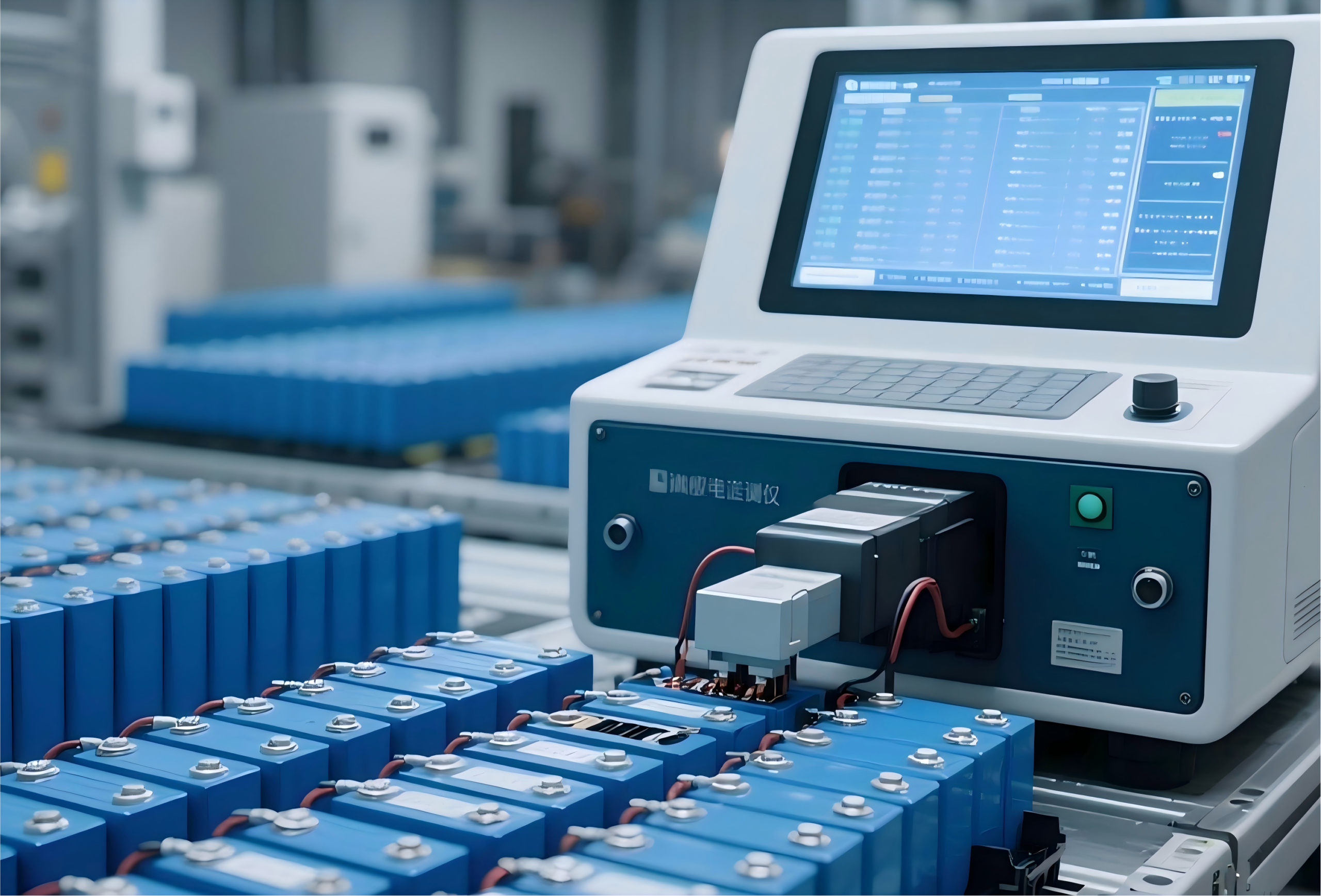
In 2025, when you charge your phone from 0 to 100% in 15 minutes, an entire system of precision electrochemistry, thermal management, and electronic control technologies is working in concert. Fast charging technology and BMS (Battery Management System) are the two core technologies of modern 3C battery packs — fast charging determines the “speed” of user experience, while BMS determines the “intelligence” of battery safety.
This article provides an in-depth analysis of 3C battery pack core technologies from four dimensions: fast charging evolution, key technologies behind fast charging, BMS three-tier functional architecture, and common BMS design pitfalls.
—
II. Fast Charging Technology Evolution
1. From 1C to 6C: A Decade of Charging Speed Leaps
Fast charging evolution is measured in “C-rate” (charge/discharge rate). 1C means charging to full in 1 hour, 3C in approximately 20 minutes, 5C in approximately 12 minutes, and 6C compresses the time to about 10 minutes.
Fast Charging Technology Timeline:
– 2015: 1C-2C fast charging became widespread (5V/2A, 9V/2A), charging time 2-3 hours
– 2018: 3C fast charging became standard in mid-range models (18W-30W), charging time ~1.5 hours
– 2021: 5C fast charging appears in flagship models (65W-120W), charging time 30-40 minutes
– 2024: 5C fast charging fully adopted in mid-to-high-end, 6C fast charging begins penetration (120W-240W), charging time 15-20 minutes
– 2026 expectation: 100W+ fast charging penetration exceeds 35%, 6C fast charging becomes flagship standard
2. Market Data
In 2025, shipments of 3C devices supporting ultra-fast charging (4C and above) exceeded 800 million units. Fast charging technology has expanded from smartphones to laptops, tablets, power tools, wearables, and other 3C product categories. By the end of 2026, the penetration rate of 100W+ fast charging in 3C devices is expected to exceed 35%.
3. Fundamental Challenges of Fast Charging
The essence of fast charging is injecting large amounts of electrical energy into a battery in a very short time, which brings three major challenges:
– Heat management: High-rate charging generates significant Joule heat, causing rapid battery temperature rise
– Electrochemical polarization: High current density intensifies electrode polarization, potentially triggering lithium dendrite growth
– Material degradation: Prolonged high-rate charging accelerates electrode material structural degradation, shortening cycle life
—
III. Key Technologies Behind Fast Charging
1. Advanced Electrolyte Systems
The core goal of fast-charging electrolytes is to reduce internal resistance and improve ion conduction efficiency. Key technology directions include:
– Novel solvent formulations: Using low-viscosity solvents (such as ethyl methyl carbonate EMC) to reduce electrolyte viscosity and improve lithium-ion migration rate
– Novel additives: Film-forming additives optimize the ionic conductivity and stability of the SEI (Solid Electrolyte Interphase)
– High-concentration electrolytes: Increasing lithium-ion concentration to reduce concentration polarization
2. Composite Conductive Agents
Traditional conductive agents (such as carbon black SP, carbon nanotubes CNT) may provide insufficient conductive networks during high-rate charging. Composite conductive agents combine multiple conductive materials (graphene + carbon nanotubes + carbon black) to build a multi-scale conductive network, significantly improving electrode conductivity and reducing polarization.
3. Anode Fast-Charging Optimization
The anode is the “bottleneck” of fast charging — during high-rate charging, lithium ions need to rapidly intercalate into the anode. If the intercalation speed cannot keep up, lithium ions deposit on the anode surface forming lithium dendrites, triggering safety issues.
Optimization Solutions:
– Silicon-carbon anode fast-charging adaptation: Through nano-sizing silicon particles and carbon coating, improving the fast-charging performance of silicon-carbon anodes
– Graphite anode orientation optimization: Controlling graphite particle alignment to shorten lithium-ion diffusion paths
– Anode structure design: Increasing anode thickness margin to prevent lithium deposition during overcharge
4. Thermal Management Design
If heat generated during fast charging is not dissipated promptly, battery temperature will rise excessively, triggering BMS protection that reduces charging speed or even causing thermal runaway. Advanced thermal management solutions include:
– Liquid cooling: Circulating coolant to remove heat, providing the highest cooling efficiency
– Phase Change Materials (PCM): Utilizing the latent heat of phase-change materials to absorb heat without additional energy consumption
– Graphene heat dissipation films: High thermal conductivity graphene films rapidly and uniformly distribute heat
– Intelligent thermal control strategy: BMS dynamically adjusts charging current based on temperature, dynamically balancing safety and speed
—
IV. BMS: The “Intelligent Brain” of Battery Packs
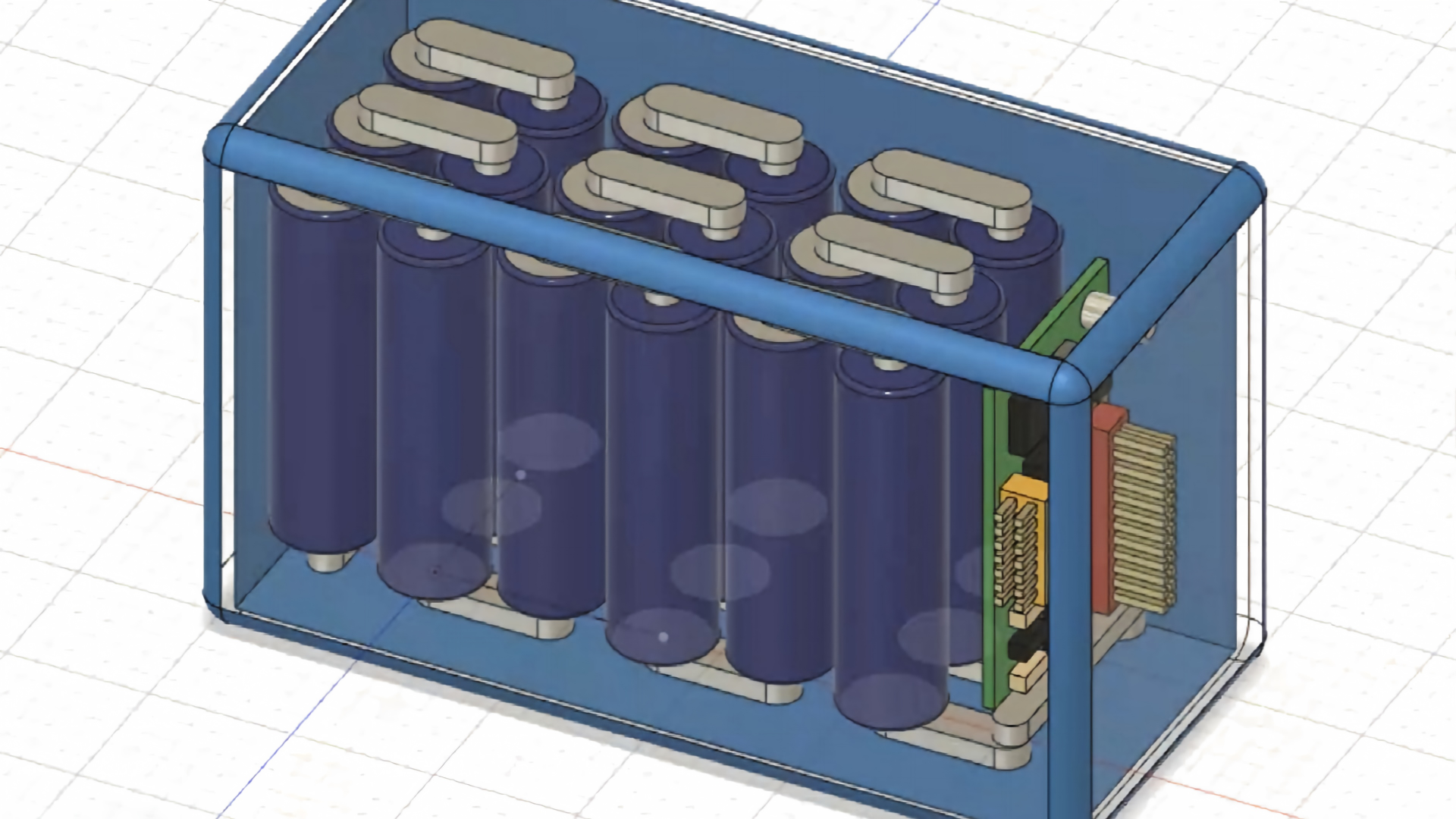
BMS (Battery Management System) is the core control unit of a battery pack, responsible for monitoring battery status, providing safety protection, and enabling intelligent management. Based on functional complexity, BMS can be categorized into three tiers.
1. Basic Protection Type BMS
Protection Functions:
– Overcharge protection: Cuts off charging circuit when cell voltage exceeds set threshold (typically 4.25V±0.05V)
– Over-discharge protection: Cuts off discharge circuit when cell voltage drops below set threshold (typically 2.50V±0.05V)
– Overcurrent protection: Cuts off circuit when discharge current exceeds set value
– Short-circuit protection: Instantly cuts off when external circuit shorts (response time <1ms)
– Temperature protection: Cuts off circuit when battery temperature exceeds set threshold
Monitoring Functions:
– Individual cell voltage monitoring
– Total current monitoring
– Temperature monitoring (typically 1-2 NTC sensors)
Communication: None
Applications: Standard consumer electronics, power banks, basic power tools
2. Smart Communication Type BMS
Added on top of basic protection functions:
– Balancing protection: Passive balancing, consuming excess energy from high-voltage cells through discharge resistors
– SOC (State of Charge) estimation: Remaining capacity percentage estimation
– SOH (State of Health) estimation: Battery health status assessment
Communication: I2C, UART
Applications: Smartphones, smart wearables, laptops
3. Advanced Management Type BMS
Added on top of smart communication type:
– Active balancing: Transferring energy from high-voltage cells to low-voltage cells through capacitors or inductors, with high balancing efficiency
– Cycle counting: Recording charge/discharge cycle counts
– Fault logging: Recording historical fault information for diagnosis and maintenance
Communication: CAN, RS485, SMBus
Applications: Power tools, industrial equipment, portable medical devices, portable energy storage
—
V. Common BMS Design Pitfalls
Pitfall 1: Unreasonable Protection Thresholds
Protection thresholds are the core parameters of BMS design. Thresholds set too high render protection functions ineffective; thresholds set too low cause frequent false triggers leading to abnormal device power-offs.
Correct Approach: Precisely set overcharge, over-discharge, overcurrent, and temperature protection thresholds based on cell specification sheets and application scenarios. Recommended overcharge protection threshold: 4.25V±0.05V; over-discharge protection threshold: 2.50V±0.05V, with fine-tuning based on actual test results.
Pitfall 2: Insufficient Temperature Sensor Coverage
Some low-cost BMS solutions use only 1 NTC temperature sensor, unable to accurately reflect temperature distribution across the battery pack. During fast charging or high-rate discharge, local hot spots may be missed, creating thermal runaway risk.
Correct Approach: Based on battery pack size and structure, reasonably arrange 2-4 temperature sensors, covering the highest temperature areas on cell surfaces and the BMS board area.
Pitfall 3: Improper Balancing Strategy
Passive balancing current is typically 30-100mA, which is too slow for large-capacity battery packs. After extended use, cell consistency deteriorates. If balancing trigger conditions are set improperly (e.g., triggering only when voltage difference >100mV), balancing effectiveness may be insufficient.
Correct Approach: For large-capacity or high-series-count battery packs, recommend active balancing solutions (balancing current 500mA-1A), and set reasonable balancing trigger thresholds (voltage difference >30-50mV).
Pitfall 4: Communication Protocol Mismatch
Communication protocol mismatch between BMS and host is a common issue. For example, BMS uses I2C but the host expects UART, or mismatched baud rates cause data loss.
Correct Approach: Clearly define communication protocol, baud rate, data format, and checksum method during the solution design phase, and conduct integration testing after BMS firmware development is complete.
—
VI. Coordinated Design of Fast Charging and BMS
Fast charging technology is not simply about increasing charging current — it requires coordinated operation of the cell, BMS, and charger. A complete fast charging solution includes:
1. Charger side: Intelligent charging protocol chip (PD3.0/QC4+/SCP, etc.), dynamically adjusting output voltage and current based on BMS feedback of battery status
2. BMS side: Real-time monitoring of battery voltage, current, and temperature, sending optimal charging parameters to the charger via communication protocol
3. Cell side: Optimized electrode materials and electrolyte formulations supporting high-rate charging
The three components work together to implement a “multi-stage fast charging” strategy — charging at maximum current during the low-battery phase (0%-50%), gradually reducing current during the high-battery phase (50%-80%), and charging at low current during the trickle phase (80%-100%), ensuring both charging speed and battery life protection.
—
VII. Conclusion
Fast charging technology and BMS systems represent the concentrated technical sophistication of 3C battery packs. The evolution of fast charging from 1C to 6C is backed by systematic innovation in electrolytes, conductive agents, anode materials, and thermal management. The evolution of BMS from basic protection to advanced management reflects the intelligent upgrade of battery packs from “passive power supply” to “active management.”
For 3C battery pack customization companies, mastering fast charging solution design and BMS development capabilities is not only a demonstration of technical strength but also a key competitive advantage for earning high-end customer trust. Finding the optimal balance between speed and safety in the coordinated design of fast charging and BMS is the continuous pursuit of every battery engineer.
[Image Notes: This article recommends 3-4 images — Fast Charging Technology Evolution Timeline, BMS Functional Architecture Diagram (Three-Tier Model), Fast Charging vs. Standard Charging Comparison Curve]
—
Data Sources & Technical References:
1. Fast charging market data (800M units of ultra-fast charging devices, 100W+ fast charging penetration rate 35%) — GEP Research, “Global and China 3C Battery Market Strategic Panoramic Analysis Report” (2026)
2. Silicon-carbon anode fast-charging performance — Guojin Securities “Lithium Battery Silicon Anode In-Depth: CVD Silicon-Carbon Reshapes Industry Chain”; GGII data
3. CVD silicon-carbon anode cycle life and expansion rate — GGII (Gaogong Lithium); Guojin Securities Research Institute
4. BMS functional tier framework — IEC 62660-2 standard and industry technical specifications
5. BMS protection threshold parameters (overcharge 4.25V±0.05V, over-discharge 2.50V±0.05V) — Generic cell specification parameter ranges
6. Passive/active balancing current ranges — Industry technical specifications